Table of Contents
Input/Output Ports A and B
There are two general purpose, logic-level input/output ports available on the TCB. We use the term logic-level here to indicate than when used as outputs these ports can only send very-low current signals to other logic devices (such as another Arduino), but they should not be used to directly turn on or off some other device! Likewise when used as inputs you should not apply a voltage to them greater than the logic level of the onboard processor, which happens to be 5 volts.
On the Lights & IO tab of the OP Config program you can choose whether the I/O port should be treated as an input or an output. If you don't intend to use these ports for anything it is best to leave them assigned as inputs because that will reduce the chance of damage in the case of an accidental short.
Using an I/O Port as an Input
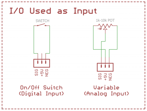
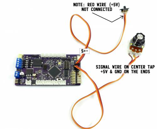
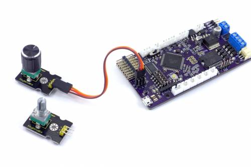
If you set an I/O port to input you can then use it as another trigger that can be applied to any function. You have the choice of two types of input: digital, which should be used with an on/off switch; or analog, which can be used with a potentiometer in the 1k - 10k range. These correspond to the two types of functions: digital (on/off functions) or analog (variable functions). If you don't want to wire your own potentiometer, Keyestudio sells what they call an Analog Rotation Sensor for cheap that can be connected to one of the TCB's inputs using a standard male-to-male servo cable, no soldering required. The Keyestudio potentiometer has a 6mm shaft, a standard size that makes it easy to find decorative knobs (just search eBay for “6mm knob”).
Each I/O port is given three pins on the TCB board - the signal pin, +5 volts, and Ground. See the schematic below for how to wire an input switch or potentiometer.
It is also possible to attach sensors to an analog input so long as they provide a signal that ranges from Ground to 5 volts. You could then create a custom function to do something with the input - we will leave that to your imagination.
Note: The digital input is considered On when the signal pin held to ground. In the schematic below, that will occur when the switch is closed.
Using an I/O Port as Output
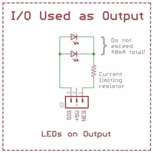
When an I/O port is set to output several new functions appear in the Function List: External Output (A or B) - On, Off, Toggle, Pulse or Blink. You can then assign any trigger to these function to cause the output to turn on, off, toggle on/off, pulse momentarily, or blink. The pulse is a momentary change in output state, if you set the output to Default High for example the pulse will momentarily bring the output to ground. The pulse and blink times can be specified in OP Config.
If you wish to connect the output to another microcontroller (such as another Arduino) you can do so directly - just connect the signal pin of the I/O port to the input pin of your other controller, and also make sure both the TCB and the other controller share a ground connection.
Each output can supply up to 40mA of current at 5 volts on the signal pin. Standard LEDs typically draw around 20mA each with the appropriate current limiting resistor, therefore you could power up to 2 LEDs on a single port (use something like LedCalc.com to calculate the correct resistor value for your LEDs).
For anything that will draw more than 40mA you will need to add an external transistor or MOSFET circuit. A simple 2n2222 transistor circuit will work and there are many schematics on the internet. Or see the Accessories page for a robust MOSFET switch schematic that you can build.
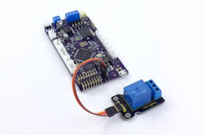
There are also various logic-level modules available on eBay that can interface directly with the TCB using a male-to-male servo cable. But be careful when choosing them, because many use a different pinout than the TCB! They can still be used, but you will need to swap the pins on your servo cable. The order on the TCB is Ground/Positive +5v/Signal. Here are some that are known to work directly:
Relay Modules
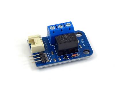
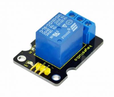
Five volt relay modules with a logic-level trigger abound on eBay and are very inexpensive. Most do not use the same pinout as the TCB. Two that do are the Keyestudio Single Relay Module and the Chivazhu 5V One Channel Relay Module. The Chivazhu is much smaller but Keyestudio has quite a few other interesting devices that will work with the TCB if you browse their listings.
With a relay module you can switch on or off a high-current device or a device that uses a different voltage source from the TCB entirely.
Buzzer Module
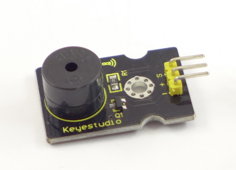
The Keyestudio Digital Buzzer Module can be attached to an output and triggered to create a beep.
