Table of Contents
Lights and General Input/Output
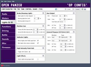 The TCB has multiple outputs intended for use with LEDs and a few other general purpose ports:
AUX: Aux Output, can be used for lights but also relays and even low current motors. This port has special settings not available to the other light ports.
- L1: Light 1, can be switched on or off. The Light 1 output has one extra feature - you can automatically have a headlight sound play whenever it is turned on or off. See the Sound tab for that setting.
- L2: Light 2, can be switched on or off, or used as a second machine gun light.
- BRK: Brake and optional running lights.
- MG: Machine Gun Light.
- GP I/O A & B: General purpose logic-level ports A & B can be configured as input or output.
The AUX and light outputs use a JST-PH connector. This is a common connector used in RC cars for LEDs. Note that none of these ports have inline resistors built in, so if you intend to drive LEDs you will need to incorporate current-limiting resistors in your wiring. Plug-and-play inline-resistor adapters may also be available. See the Lights page for more information about the hardware.
The General Purpose I/O ports are logic-level which means that, unlike the AUX and light outputs, they can not provide very much current at all - about 20mA max. Do not try to drive an LED directly from these ports! See the I/O Ports page for more information on hardware limitations.
Brake and Running Lights
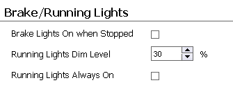 It is important to understand that the brake and running lights are the same light. When the brake light is on, the lamp will be at 100% brightness. When the “running” light is on, the lamp will be at some dim level that you determine. You can eliminate the running-light effect by setting the dim level to 0 or simply don't assign a trigger to turn it on. The brakes on the other hand do not need a trigger to operate - they will always come on automatically whenever the vehicle is braking.
Brake Lights On when Stopped
As mentioned, the brake lights will always come on (light to 100% brightness) when the vehicle is braking. But if you check this option, the brake lights will also automatically come on whenever the vehicle is stopped and the engine is running.
Running Lights Dim Level
When brake lights are not active, you can choose to turn on or off “running” lights, which are simply the brake lights set to a lower brightness level as specified here. Running lights do not turn on automatically, you need to assign a trigger (such as a switch on your transmitter) to one of the Running Lights functions. Unless you check the next setting - then you don't need a trigger:
Running Lights Always On
If you check this option, the running lights will always be on. In other words, the brake lights will always be on at the dim level specified until braking actually occurs, at which point they will be set to full brightness until braking action stops, and then they will return to the dim level. Use this option if you want running lights but don't want to assign a trigger to them.
Machine Gun Lights
Blink Interval
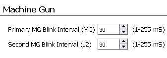 This setting is the speed in milliseconds (1,000 mS = 1 second) that the machine gun light blinks on and off. There are two intervals, one for the primary machine gun (LED plugged into MG port), and another for the optional second machine gun (LED plugged into L2 port).
Lights Used as Indicators
Blink All Lights When Radio Signal Lost
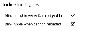 Check this box to blink every light (L1, L2, BRK, MG, APPLE hit LEDs, and the onboard red and green LEDs) when the TCB detects a loss of radio signal. If you uncheck this option, the onboard red and green LEDs will still blink on loss of radio signal, but the others will not.
Note: the TCB may not be able to detect a loss of signal in all cases. If your receiver is set to continue transmitting data even when the signal is lost (“failsafe receiver”), then the TCB will have no way of knowing the radio is off. For that reason, it is actually better if you can disable any failsafe on your receiver.
Blink Apple when Cannon Reloaded
If checked the LEDs in the IR Appple will blink briefly after the cannon reload time has expired, this can be useful in IR battle to let you know the instant when you are able to fire once more. The cannon reload time is dependent on your selected weight class, discussed on the Battle tab.
High Intensity Flash Unit
Trigger with Cannon
 If checked, the High-Intensity Flash output (FLASH on the TCB) will automatically be triggered when the Cannon Fire function is called. If unchecked, you can still trigger the flash unit by itself by using the High Intensity Flash function.
Light Effects
Flicker Headlights during Engine Start
 This option attempts to create the illusion of intermittent/inadequate voltage on certain lights during the time when the engine is being started. This is something that might have been seen on WWII-era tanks, the same as it might have been seen on WWII-era cars. This effect is applied to the Aux Output and the Brake Lights output. This may seem strange, why isn't it applied to the Headlights output (Light 1)? The reason is because the Light 1 output on the TCB unfortunately does not have the ability to be set to any brightness level, it can only be turned full on or full off. A realistic flickering effect can not be created under those conditions. Therefore, if you wish to use this effect, know that you will need to connect your headlight LEDs to the Aux Output port instead of the Headlights port, and you will need to add the appropriate function triggers to turn off/on the Aux Output from your transmitter.
Here is how to use this effect:
- Check the option to “Flicker lights during engine start”
- Specify a “Transmission Engage Delay” time on the “Driving” tab of OP Config. You should set this delay to be equal to the length of time of your engine startup sound. When the engine is started, the engine start sound is played, this delay begins, and during the delay the transmission will not be engaged (the model can not be moved), and the LEDs connected to the Aux output as well as the Brake output will flicker.
- Of course, the lights will only flicker if they were turned on before the engine start began. For the Aux output that means you have turned it on using a Function Trigger. For the brake or running lights, that means you have checked either the “Brake Lights On when Stopped” option or the “Running Lights Always On” option.
- When the “Transmission Engage Delay” has expired, your engine start sound should have also completed. At this time the transmission will automatically be engaged (allowing you to begin driving), and the Aux Output and Brake Lights will cease to flicker and return to full brightness.
More things to note: the Aux Output can be used for many different purposes, not all of which are compatible with this effect. If you set the Smoker Type to “Separate Heat and Fan,” or if you set the Aux Output to “Auto Flash with Cannon,” this flickering effect will be disabled. In the first case the Aux Output is reserved to drive the smoker fan, in the second case the Aux Output is being used with a barrel flash LED. There may be other combinations that do not make sense but which are possible for the user to create, so use common sense.
Aux Output
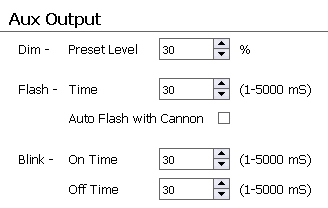 The Aux Output uses the same JST-PH connector as the other light ports, and it can be used to drive an LED the same as the others, just assign a trigger to turn it on or off. However this port also has several other options not available to any other port. The port can be dimmed to a preset level, or you can even assign a variable (analog) trigger to adjust the dim level on the fly. The Aux output can also be triggered to Flash (blink once) or Blink continuously until turned off.
The Aux Output port is also unique in that it is protected with a “flyback” diode. This makes it suitable for turning on/off an inductive load such as a 5 relay. It can even be used to drive a low-current motor.
Note: just because the settings below are filled in, doesn't mean the Aux Output will actually do anything. To make it come on to a preset Dim level, or Flash, or Blink, you must assign triggers to those functions on the Functions tab.
For more information on the hardware limitations of this port, see the Aux Output page.
For a complete list of all functions related to the Aux Output, see the Functions and Triggers page.
Dim - Preset Level
The Aux Output has a function called Aux Output - Preset Dim Level. If you trigger this function it is basically the same thing as turning the output On, except it will turn on to the preset dim level you specify here instead of to 100%.
Flash - Time
The Aux Output has two flash functions called Aux Output - Flash and Aux Output - Inverse Flash. The first function will cause the Aux output to be held low normally, and the Flash function will briefly bring the output high. The Inverse Flash function does the opposite, it sets the output high by default, and when the Inverse Flash function is called the output is held to ground briefly. In either case, the output will be “flashed” for the length of time in milliseconds that you specify here (1,000 mS = 1 second).
Auto Flash with Cannon
If this box is checked, the Aux Output will automatically be flashed (output brought high) whenever the cannon is fired, no function trigger needs to be created. If your muzzle flash is a simple LED, connect it to the Aux Output and check this option. But if you are using a Taigen High Intensity Flash unit, connect it to the dedicated Flash port on the TCB instead, in which case this Aux output can be used for other purposes. Note: if you check this option, the “Flicker Lights during Engine Start” option is disabled (because it would create a conflict with the use of the Aux output).
Blink - On and Off Time
The Aux Output has functions called Aux Output - Blink and Aux Output - Toggle Blink. The first function will start the Aux Output blinking indefinitely until you trigger the Aux Output - Turn Off function. The toggle function will toggle the blinking effect on and off each time it is triggered. Here you can set precisely both the on and off times that make up the blinking effect.
General Purpose Input/Output Ports A & B
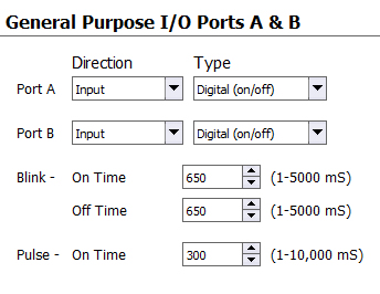 The A & B ports are general purpose, logic-level ports that can set to input or output depending on your needs.
Note: if you don't intend to use ports A & B, leave them as inputs (digital or analog doesn't matter). As inputs there will be less chance of an accidental short causing damage to the onboard processor.
Note: for more information on wiring input switches, potentiometers, or output devices to these ports, please see the I/O Ports page.
Using the I/O as Inputs
If you set Port A or B to input they will show up in the Trigger Source list and you can use them to trigger any function.
Digital Input: If you want the input to be on/off, set the input type to “Digital (on/off)” and wire a switch such that the signal pin is connected to ground when the switch is in the on position, and disconnected when in the off position. You can now use this digital input to switch or toggle any digital function in the Function List. For example, you could use this as a physical switch on your model to turn on or off the engine if you didn't want to control that from your transmitter.
Analog Input: If you want the input to be variable, set the input type to “Analog (variable)” and attach a potentiometer of 1k - 10k resistance to the port such that the signal pin is connected to the center tap of the potentiometer, and the two ends of the potentiometer are connected to +5v and Ground. Now you can use this analog input to adjust any analog function in the Function List. For example, you could install a potentiometer on your model to adjust the acceleration or deceleration constraint level, or both (you can assign more than one function to a single trigger).
Using the I/O as Outputs
Alternatively the A & B ports can be set to Output. In this case you have the option of setting their default state, either High (pin at +5 volts) or Low (pin held to Ground). When set to output, several new functions will be created in the Function List:
- External Output A/B - Toggle
- External Output A/B - Turn On
- External Output A/B - Turn Off
- External Output A/B - Pulse
- External Output A/B - Blink
You can then assign a trigger to these functions and in so doing control the output of these ports. The first three functions are self-explanatory, the fourth function, “Pulse,” will briefly set the output pin to the state opposite its default. For example, if you had set Port A to Output with Default High, the pin will be kept high (+5 volts) normally and the Pulse command would cause it to briefly be held low (to ground). If you set the output to Default Low, the pin will be kept low (at ground) normally and the Pulse command would cause it to be temporarily brought high (+5 volts). The pulse duration can be set by the “Pulse - On Time” value (the pulse time is shared by both outputs).
The fifth function will cause the output to blink and blinking will continue until you call the “Turn On” or “Turn Off” function. The blink rate can be set by using the “Blink - On Time” and “Off Time” values (the blink rate is shared by both outputs).
What you do with these outputs is up to you, but remember these are logic-level outputs! The maximum current draw of each output signal pin is 40mA. This may be enough to power one or two standard LEDs, but not much of anything else. Instead consider the outputs like signals, and the signals can tell some other more powerful circuit to do something, or they could be used as direct inputs into another microcontroller (such as another Arduino).
If you want to use these outputs to turn on a lamp, or a relay, or some other object that draws more than 40mA of current, you will need to use a driver circuit. You can find a schematic for a MOSFET driver adapter on the I/O Ports page. Alternatively you may want to use the Aux Output (see above) which is capable of driving a load directly.