Table of Contents
Accessory Boards
These are additional DIY designs that can be used with the TCB.
Tamiya Plug-and-Play Adapters
The TCB is pin-compatible with many Tamiya tank accessories, but not plug-compatible. Tamiya uses a miniature plug called the Micro-Latch, made by Molex. Although it works well, it is difficult to source and even more difficult for hobbyists and tinkerers to assemble their own cables. The TCB instead uses JST XH-series plugs for the smoker, mechanical recoil, apple, and IR LED connections. Pigtails for these are cheap and abundant on eBay, not to mention widely in use by Chinese tank model manufacturers such as Heng-Long and Taigen.
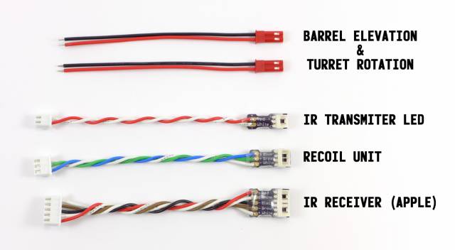
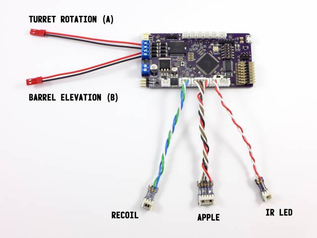
Detailed information about each device (recoil units, IR apples, etc) and how to adapt it to the TCB can be found on those respective pages of the wiki. But if you have a Tamiya tank, the 5 adapters described below will let you plug-and-play your turret rotation motor, barrel elevation motor, recoil unit, IR receiver (apple), and IR transmitter LED without any modification.
The files below describe how to assemble the three adapter boards. The red plugs used for the turret motors are just JST pigtails, you can easily find them for cheap on eBay by searching for “JST Plug.”
- Eagle Schematics (ZIP)
- Bill of Materials (PDF)
(In OP Config, set the turret rotation and barrel elevation motors to Built-in Driver)
LED Current Limiters
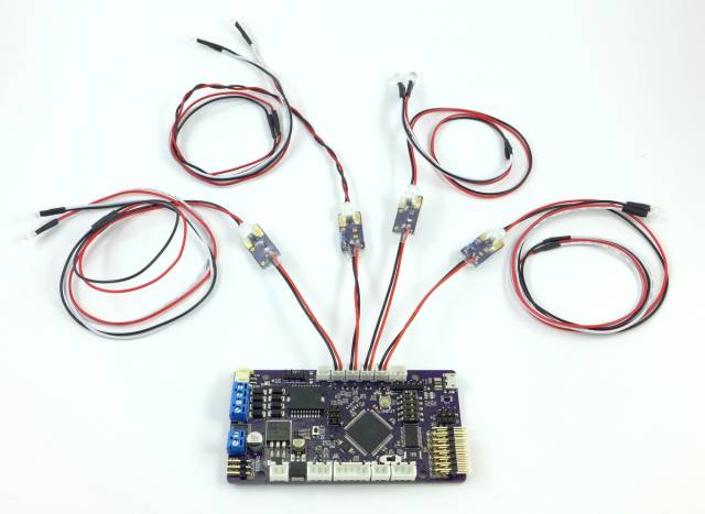
Because the TCB does not include current-limiting resistors on its four Light outputs, nor on the Aux Output which can be used for a 5th light, you may need to add your own depending on which LEDs you use. As discussed on the Lights page, there are some LEDs sold by Yeah Racing for the RC car market that are direct plug-and-play with the TCB and already have the appropriate current limiting resistors built in to their wiring. But for custom jobs you need to determine the appropriate resistor and implement it yourself.
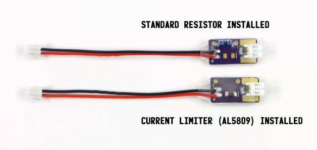
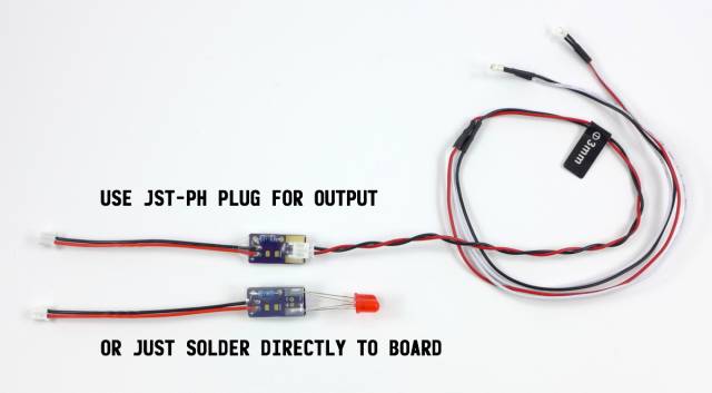
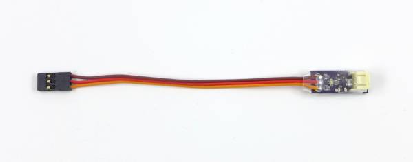
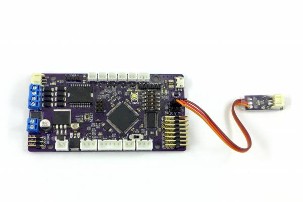
These small boards make that job easier. On one end solder the leads from a 2-pin JST-PH pigtail (a pigtail is a plug with wire leads already attached). These are cheap and easy to find on eBay, just search for “JST PH 2 pin connector.” This pigtail will then plug into any of the TCB's light outputs.
On the other end of the board solder a right-angle JST-PH connector (JST Part No. S2B-PH-K-S - Digi-Key link, or just search eBay again for “JST PH 2 pin right angle”), or you can use the large solder pads on both the top and bottom of the board to solder LEDs or wires directly to the board.
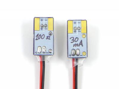
On the board itself you have two choices for current limiting. Use any typical 1/4 watt through hole resistor of whatever value you need (if you're not sure, use a resistor calculator such as this one). Or you can attach one of the very convenient current-limiting ICs such as the Diodes Inc AL5809 in either SOD-123 or PowerDI 123 footprints (DigiKey link). These handy “diodes” restrict current to a maximum level and come in values from 15mA to 150mA. For most common LEDs the 20mA current limiter would work for a single LED and 40mA for two wired in parallel.
The bottom of the board is entirely white silkscreen for writing a small note with a fine-tipped Sharpie - such as the resistor or current limiter value, so you don’t forget.
When done assembling use clear heatshrink over the entire board. Heatshrink that is approximately 3/4“ (18-20mm) wide when laid flat works well.
- Eagle Schematic (ZIP)
MOSFET Switch
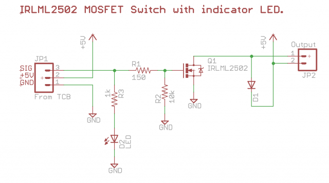
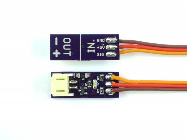
The TCB has two general purpose I/O ports that can be set either to input or output. When used as outputs they provide a logic-level (5v) digital signal (on/off). This signal can be attached directly to another microcontroller (such as an Arduino), but as each port can only source 40mA on the signal pin, they are inadequate for switching most loads other than possibly one or two standard LEDs. If you want to drive a relay or some other kind of device from these outputs, you will need to implement a transistorized switch. Of course, remember also that the TCB already has four light outputs for lights, and a special Aux Output that can be used to drive a relay directly - so most people will never need to use these alternate outputs. But if you do, the sample circuit below shows a MOSFET driver circuitry with flyback protection that can be plugged into one of these outputs and used to drive an LED or a 5v relay.
- Eagle Schematic (ZIP)
- Bill of Materials (PDF)
