Table of Contents
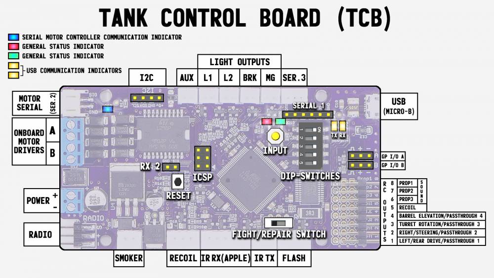
Board Layout
Left Side
Motor Serial
Also known as Serial Port 2, this is reserved for communicating with serial dual motor controllers such as the Dimension Engineering Sabertooth series or the Pololu Qik controllers. The plug is a 2-pin JST-PH. Up to two controllers can be attached to this port allowing control of up to 4 motors at the same time (left and right drive motors, turret rotation and barrel elevation), or any combination thereof. For 1/16th scale tanks we personally prefer using a Sabertooth controller to power the main drive motors, rather than two individual hobby ESCs. See the Serial Motor Controllers page for more information on these controllers, and see the Motors tab of OP Config for how to select the control type for each of your motors.
Onboard Motor Drivers A & B
These screw terminals can be used for attaching two motors to be driven by the TCB's two onboard speed controls. These motor drivers can only supply 2 Amps max each! This means for 1/16th scale models, they will not be adequate for powering the main drive motors (1/24th scale would be fine). They are however perfect for driving the turret rotation and barrel elevation motors of 1/16th scale models. See the Built-In Controllers page for more information on using these outputs, and see the Motors tab of OP Config for how to select the control type for each of your motors.
Power
This screw terminal is where you attach battery power to the TCB. It is reverse-polarity protected. The TCB can accept any voltage from 7-15 volts. See the Power Supply page for more information.
Radio
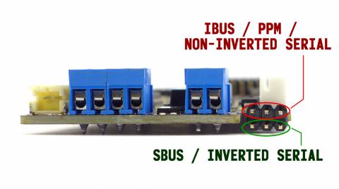
The TCB actually has dual radio connectors - one is located on the top of the board and the other on the bottom. The top connector is used for PPM or iBus receivers, and the bottom connector for SBus receivers (the bottom connector inverts the signal before feeding it into the processor). The easiest way to connect your receiver is with a standard male-to-male servo extension cable. The TCB automatically detects the type of receiver attached. As a rule, PPM receivers can have up to 8 channels, iBus supports up to 14 channels, and SBus receivers provide up to 16 channels. See the Receiver page for more information on receiver types including recommendations for receivers and radios.
Right Side
USB
Connect the TCB to your computer using a standard Micro-B USB cable. This is an extremely common plug size used in millions of smartphones, so chances are you already have a cable. The “OP Config” desktop software is then used to communicate with the TCB - from there you can change any of the scores of settings, and you can even update the firmware when new releases become available. See the Connecting to the TCB page for more info.
GP I/O A & B (General Purpose Input/Output A & B)
These connections are for advanced users. Each one can be configured individually as either an input (and furthermore as a digital input or an analog input), or as a line-level output. When used as an input you can connect a switch or potentiometer and then assign those to any of the dozens of available functions - for example, you may want a physical switch on the model to start/stop the engine, or a potentiometer to adjust the acceleration or deceleration constraints. When used as an output, any other trigger (such as channels on your radio) can be assigned to the output, which will then emit a digital on/off signal. These outputs should not be used to directly drive devices - if you want to use them to switch on a light or a relay for example, you will need to use an intermediate transistor circuit. But the signals can be attached directly to another micro-controller (such as an Arduino) that has 5 volt tolerant input pins. For complete details on these versatile I/O ports, see the I/O Ports page. For their settings in OP Config see the Lights & I/O tab.
RC Outputs
The TCB provides 8 RC outputs. Some are reserved for specific functions, others can be used for multiple purposes depending on settings you make in OP Config. From top to bottom:
8 - Prop1 (proportional 1) to a sound unit (such as the Benedini TBS). This signal will represent the engine speed.
7 - Prop2 (proportional 2) to a sound unit. The signal works as a 12-position switch for selecting 12 different sounds.
6 - Prop3 (proportional 3) to a sound unit. This works as a 2-position switch for selecting two additional sounds.
(See the Sound Unit page for more information on connecting and configuring a sound unit with the TCB.)
5 - Used exclusively for driving a recoil servo. See the Servo Recoil page for more, and the Motors tab of OP Config for configuration options.
4 - If using a servo or ESC to control the barrel elevation movement, it will plug in here. Otherwise this output can be used as a direct channel pass-through from your transmitter.
3 - If using a servo or ESC to control the turret rotation movement, it will plug in here. Otherwise this output can be used as a direct channel pass-through from your transmitter.
2 - If using a servo or ESC to control a tank, the right drive motor will plug in here. If the TCB is set to Halftrack or Car mode, this output will be used to control a steering servo. If none of those apply, this output can be used as a direct channel pass-through from your transmitter.
1 - If using a servo or ESC to control a tank, the left drive motor will plug in here. If the TCB is set to Car mode, you can use this output for the single drive motor ESC. If none of those apply, this output can be used as a direct channel pass-through from your transmitter.
(For RC Outputs 1-4, see the Motor Control page for more information on the various motor control options as well as the Motors tab of OP Config for the configuration settings.)
Top
I2C
The I2C port is not presently used for anything but is available for developers.
Aux Output
The Aux Output is a PWM-capable 5 volt digital output with flyback protection. It can be used to control a light with many different effects, a relay, or even a small motor. See the Aux Output page for more information on this special output, as well as the Lights & I/O tab of OP Config for configuration settings.
L1 - Light 1
Light 1 is a 5 volt digital on/off port used to control a lamp or LED. If you have headlights you would typically attach them here. See the Lights page for more information, and the Lights & I/O tab of OP Config for all the light settings.
L2 - Light 2
Light 2 is a 5 volt digital on/off port used to control a secondary light - this is useful if your tank has a map light. See the Lights page for more information, and the Lights & I/O tab of OP Config for all the light settings.
BRK - Brake Light
The Brake Light is a 5 volt digital on/off port used to control brake and “running” lights from a single port. Running lights illuminate at partial brightness, when the brake lights come on they go to full brightness. The brake effect is automatic whenever the tank is braking (deceleration constraints will need to be set for braking to be needed, see the Driving tab in OP Config), but there are various other settings that can be made. See the Lights page for more information, and the Lights & I/O tab of OP Config for all the settings.
MG - Machine Gun Light
The Machine Gun light is a 5 volt digital output used specifically for creating a machine gun effect - in other words, the light blinks rapidly. The blink rate can be set in OP Config on the Lights & I/O tab. If you need a second machine gun it is possible to create one with the Aux Output.
Serial 3
The Serial 3 port is an extra communication port available for developers. It only has the transmit pin (not receive). It is also automatically disabled whenever an SBus receiver is used (the Serial 3 receive port is used for SBus decoding at a non-standard baud rate, hence the transmit pin is of little use in that case).
Bottom
Smoker
Taigen/Heng-Long smokers are direct plug-and-play into the Smoker port on the TCB. If not used for a smoker this output can be re-purposed as a uni-direction speed controller for motors of up to 3 amps. See the Smoker page for details on the hardware, and the Motors tab of OP Config for all the settings.
Recoil
The 3-pin Recoil connector is used for controlling mechanical recoil units (for example the Taigen/Asiatam units or the Tamiya version), or it can also be used to control a Heng-Long/Taigen Airsoft unit. The Taigen/Heng-Long units use the same plug but they must first be re-wired. The Tamiya recoil units need no modification, but you must use an adapter because Tamiya uses an odd plug. See the Mechanical Recoil and Airsoft pages for more information, including instructional videos. And see the Motors tab of OP Config for settings.
IR Receiver or "Apple"
This 5-pin plug is used to connect an IR receiver unit such as the Tamiya Apple (#53447). Three pins are used for the IR receiver and two pins to control the hit-notification LEDs. The Tamiya Apple is plug-and-play with an adapter (Tamiya uses non-standard plugs). Heng-Long/Taigen receivers do not include the hit-notification LEDs so they only have three pins, but they can still be plugged directly into this port. See the Infra-Red page for all the hardware details, the Battle tab of OP Config for the multitude of IR battling options, and our IR Battle page for a general overview of IR battling and how it works.
IR Transmitter
This 2-pin plug is used to drive an infra-red LED that will transmit the IR signal during battle. Tamiya IR LEDs are plug-and-play with an adapter. A switch above this plug lets you select between Fight (full power) and Repair (reduced power) mode. See the Infra-Red page for information about IR emitters, the Battle tab of OP Config for the multitude of IR battling options, and our IR Battle page for a general overview of IR battling and how it works.
Flash
This 3-pin plug is used to connect Taigen/Asiatam high-intensity flash units. These units come with a 5-pin plug of which only 3 pins are actually used. It is very easy to change the plug to 3-pin and then they are plug-and-play. See the High Intensity Flash page for more information including an instructional video.
Other Connections
Serial 1
Unlike the USB port (which can only be used with a USB cable), or the Serial 2 port (reserved for serial motor controllers), or the Serial 3 port (transmit only and disabled when using serial data receivers), the Serial 1 port is fully functional and open for any use. All 6 pins for a standard FTDI connection are broken out, which make it easy to connect it to a computer with an FTDI adapter. Even better, it is plug-and-play compatible with certain Bluetooth adapters for wireless communication with your TCB, including updates, viewing debug messages, and even flashing new firmware. This can be very convenient when your TCB is installed deep inside your model and is difficult to access. Flipping Dipswitch #5 to the Off position will automatically cause the TCB to perform all communication through the Serial 1 port instead of the onboard USB port. See the Bluetooth page for more information on creating a wireless link.
ICSP
You should almost never need to use the 6-pin ICSP (In-Circuit Serial Programmer) port unless you are an advanced developer. If you already know what ICSP is, you don't need to read an explanation here. If you don't know what it is, you definitely don't need to worry about it!
Switches
Dipswitches

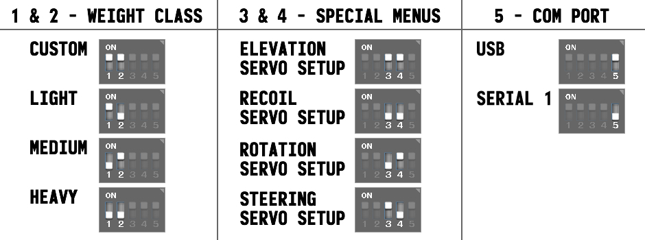
The TCB has 5 dipswitches. Dipswiches 1 & 2 select the vehicle's weight class for IR battle, meaning you don't need a computer or any equipment to change your weight class in the field. Dipswitches 3 & 4 select one of 4 Special Menus, the menus are then entered by holding the Input button for 2 seconds. Dipswitch 5 sets the currently-active communication port - see Connecting to the TCB for more.
Fight/Repair Switch
The Fight/Repair switch is used to select between normal IR battle mode or “bergepanzer” mode (repair). In the Fight position, full battery voltage is applied to the IR transmitter through a very low resistance 3.3 ohm resistor to prevent burnout. Keep that in mind if you use a non-standard battery greater in voltage than the typical 6 cell NiCad or 2S LiPo. In the Fight position, the active cannon IR protocol will be transmitted. In the Repair position (some people call this “bergepanzer” mode from the German word for armored recovery vehicle) the IR protocol will automatically be changed to the selected Repair protocol and the transmit power will be lowered considerably by routing the signal through a 1k ohm resistor. In testing with stock Tamiya LEDs a repair hit could be taken from as much as 4 feet away but only if there was perfect alignment between the IR transmitter and receiver. Try to fire the low power repair signal from any sort of angle and the distance is reduced considerably.
In summary, you can quickly convert your model from a fighting to a repair tank simply by flicking a switch, and you can even do so on the fly. No reprogramming and NO JUMPERS required!
The TCB is compatible with a wide range of IR protocols in addition to Tamiya, both for cannon fire as well as repair and machine gun signals. See the Battle tab in OP Config for more.
Buttons
Reset Button
Pressing the Reset button will cause the TCB to reboot. It is not often needed but some settings such as your tank's weight class (set by Dipswitches 1 & 2) are only applied on startup, and rebooting lets you apply a change without unplugging the device.
Input Button
When held for 2 seconds the Input button will let you enter one of 4 special menus on the TCB. Which menu is determined by the position of Dipswitches 3 & 4 (see below). For more information see the Special Menus page.
In normal operation, when the Input button is pressed briefly it will cause a comprehensive dump of status information to the currently-selected communication port: the USB port if Dipswitch #5 is in the On position, or out the Serial 1 port if Dipswitch #5 is in the Off position.
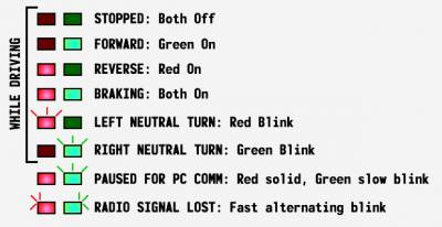
You can also perform a factory reset of the device by holding the input button for 4 seconds while first applying power. The easiest way to do this is to power the TCB, then hold down the reset button to turn off the processor, hold down the input button, let go of the reset button, and keep holding the input button for 4 seconds. While it is held down the Red LED will be on solid. When 4 seconds have passed, both the Red and Green LEDs will blink slowly 5 times in a row - this lets you know that all settings have been restored to their factory default. You will want to go through Radio Setup again after you do this.
Onboard LEDs
Red & Green LEDs
 The Red and Green LEDs can be used to indicate the board status. While driving, the Green LED indicates forward movement, the Red reverse movement, and both on at once indicate braking. The LEDs are off when stopped, while the Green LED blinks during neutral turns to the right and the Red LED blinks during neutral turns to the left (if neutral turns are enabled). When not driving, a solid Red LED indicates the TCB is not in normal operation mode: either because it is still booting up, or because the user has entered a Special Menu, or because it is paused in order to communicate with a PC. In Special Menus the Red LED will remain solid and the Green LED may blink to indicate certain information or steps. When communicating with the PC, the Red LED will remain solid and the Green LED will blink slowly.
Blue LED
The blue LED will flicker whenever the TCB is transmitting instructions to a serial motor controller.
Orange LEDs
The orange LEDs will flicker whenever the TCB is transmitting or receiving data over the USB port. The LED closest to the USB connector is the receive LED - it will light up whenever the computer is sending data to the TCB. The other orange LED is the transmit LED and will light whenever the TCB is sending data to the computer.

