Table of Contents
Miscellaneous Settings
Low Voltage Cutoff
 Low voltage cutoff is a feature to help protect the battery in your model from over-discharge. This can be especially important for lithium-polymer (LiPo) batteries, which can be permanently damaged if their voltage drops too low. With LVC enabled, if pack voltage drops below the level specified all tank movement will be disabled and all lights attached to the TCB, as well as the two onboard red and green LEDs, will begin to blink in a pattern from fast to slow, over and over again.
Enabled
Check this to enable LVC. If unchecked, the TCB will continue to operate no matter how low your battery voltage becomes!
Cutoff Voltage
Specify the voltage below which you want vehicle operation to cease. If you are using lithium-polymer batteries (LiPo) a conservative level would be 3.2 volts per cell. In other words if you are using a 2S LiPo, a cutoff voltage of 6.4 volts would be reasonable (but you may wish to set it even higher).
For NiCad and NiMH batteries 1 volt per cell is a typical cutoff level, though you may find your model getting sluggish even before it gets that low. The standard Tamiya/Heng-Long NiCad packs that are marked “7.2v” are made up of 6-cells. When fully charged they can actually read anywhere from 7.8 to 8.4 volts, depending on the charger you are using. By the time they get down to the actual 7.2 volt rating they are nearly discharged, although they can go down to 6 volts without damage. You can specify cutoff of 6.0 volts but as already mentioned you will probably notice the model slowing down even before that level.
Note: Especially in the case of LiPo batteries, the voltage you measure when the pack is at rest (not powering anything) will be higher than it actually is under load. The TCB measures voltage under load when deciding if the LVC level has been reached. If afterwards you take the battery out and measure the voltage you may find it to be higher than the LVC level you specified. That is because once the load was removed the pack's voltage rebounded. But rest assured it actually did reach the cutoff level at some point while the model was moving if the TCB entered cutoff mode.
Baud Rates
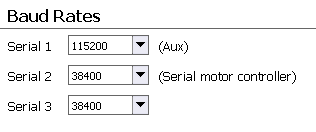
 There are 4 serial ports on the TCB. One is dedicated to the USB output and is hardcoded to a baud rate of 115,200. The baud rates for the other three can be adjusted.
Serial 1 - Aux
The Serial 1 (Auxiliary) port can be used for any purpose. It features the full compliment of pins required to connect a Bluetooth module or an FTDI adapter. Another potential use is to connect a serial-capable inertial-measurement-unit. All common baud rates can be selected.
Serial 2 - Serial Motor Controller
The Serial 2 port is dedicated to communication with serial motor controllers. It has its own 2-pin JST-PH header on the TCB board. It can only transmit serial data, it can not read serial input. The default baud rate is 38400 and unless you have a specific reason to change it you should leave it at 38400. Not all rates are compatible with all devices, but 38400 is known to work well with all. In general slower rates typically perform worst, but some controllers (such as the popular Sabertooth 2×5) are not compatible with the highest rate of 115200. Again, almost all users will be best served by leaving the rate at 38400.
Serial 3
The Serial 3 port has the reception and transmission pins routed to two different locations. The reception pin is attached to the RADIO input header and is used to read data from serial receivers such as those capable of SBus or iBus transmissions. If a serial receiver is detected, any baud rate setting here will be automatically overwritten with required baud rate for the protocol found (100,000 for SBus, 115,200 for iBus), and transmission out the SER.3 header will be disabled. If no serial receiver is detected (for example, the receiver is PPM instead), the Serial 3 port is available for transmission at whatever baud rate is specified here. Transmission will be out the SER.3 header, which is a 3-pin JST-PH connector that provides the transmission pin as well as +5v and Ground. This header could be used to attach a serial-enabled LCD such as those sold by SparkFun or Adafruit. At present no LCD code is implemented in the TCB firmware, and because the transmission port is disabled when serial receivers are used, this port is of little practical use except to developers.
Debugging
 If debugging is enabled, the TCB will send informative messages out whichever serial port is selected by Dipswitch #5. If Dipswitch #5 is in the On position, messages will go out the USB port. If it is in the Off position, messages will go out the Serial 1 port (Serial 1 can be used with a Bluetooth adapter). The easiest way to see debugging messages is to use the Snoop feature of OP Config to display them (see the Firmware tab for more information on snooping). Or if you are developing with the Arduino IDE you can see these messages using the Arduino Serial Monitor.
Debugging is very useful for troubleshooting and is enabled by default. However if your TCB is running as expected and all functionality has been verified, you may want to disable debugging messages because they do slow down program operation. The effect is unlikely to be noticeable, but if you are not using the debug feature anyway, go ahead and turn it off.
Scout ESC Settings
 Here you can adjust the maximum current limit of any Scout ESC attached to your TCB. By default the Scout will stop the motors when current draw exceeds 12 amps total for both motors, since this is the Scout's limit for continuous operation without additional cooling. However the Scout can theoretically operate at up to 30 amps with sufficient heatsinking and cooling. Or you might wish to restrict the current limit to an even lower number in order to protect the drive-train on your model, if you already know the stall current of your motors. Set your desired maximum current here, and the TCB will instruct the Scout not to exceed that level.
Sabertooth Baud Rate Tool
 Not all Dimension Engineering controllers operate the same way. The Sabertooth 2×5 can automatically detect the baud rate of the master device (in this case the TCB). If you have a 2×5 controller you do not need to do anything with regards to the baud rate and you can skip this section.
The other Sabertooth models (2×12, 2×25, 2×32 and 2×60) must have the baud rate set through special serial commands. This requires a utility such as the one provided here. Once the baud rate has been set appropriately the Sabertooth will remember it, so the utility only needs to be run once.
If you own one of the Sabertooth controllers that needs this setup, connect it to the TCB and then connect your TCB to your computer via USB, and finally open a connection to the TCB within OP Config. Select the baud rate you want for the Serial 2 port in the Baud Rates section. Most users should set this to 38400. Now click the “Set” button and the TCB will configure the Sabertooth to use that rate.
Pololu Qik Configuration
 If you are using a Pololu Qik dual-motor serial controller (either the 2s12v10 or the 2s9v1), a one-time configuration routine may need to be run to configure it for use with the TCB. The default settings used by Pololu from the factory should work fine with the TCB so long as the Qik is used to control the main drive motors. But if you want to use a Pololu Qik controller to drive the turret motors, or if you have a Pololu Qik controller that had its default settings changed, you will need to re-configure it.
To configure a Pololu Qik controller, connect it to the TCB's Motor Serial port and provide it with power from a battery. OP Config must also be actively connected to the TCB via USB or Bluetooth, otherwise the configuration buttons will be disabled.
Configure Pololu for Drive Motors
Click this button to configure the attached Pololu device for use with drive motors. The red LED on the Pololu Qik controller will blink briefly and that's it. The Pololu will now respond to drive commands if you have the Drive Motors type set to Pololu Serial ESC on the Motors tab.
Configure Pololu for Turret Motors
Click this button to configure the attached Pololu device for use with turret motors. The red LED on the Pololu Qik controller will blink briefly and that's it. The Pololu will now respond to turret rotation and barrel elevation commands if you have either of those motor types set to Pololu Serial ESC on the Motors tab.
