Table of Contents
Building a Board
The official OSL board is a through-hole design that is easy for anyone with basic soldering experience to assemble.
The bare PCB for the OSL board can be purchased from OSH Park:
Open Source RC Lights v1.7
Alternatively, since this is an open source project, you are free to take the Eagle files posted on the Downloads page to your favorite fab house.
Components
Components to populate the board are listed in the Bill of Materials (BOM) available on the Downloads page.
Atmega328 Processor
The processor used on this project is the ATmega328, the same processor used on millions of Arduinos. One thing to know is that the processor must have a “bootloader” program loaded onto it before it can communicate with the Arduino IDE. There are tutorials online for how to do this, but the best approach is to buy chips with the bootloader pre-installed. Here are two sources, but there are many others:
ATmega328 with bootloader - SparkFun
ATmega328 with bootloader - Adafruit
Current Limiting Resistors
The values for resistors R11 through R18 on the board can be selected by yourself to match the LEDs you intend to use. See the LED Notes page for more information on selecting the correct resistors. If you are unsure what value to use, 100 ohms is usually a good choice. Or, you can simply jumper across these points with a small piece of wire, and install resistors in the cables leading to your LED lights.
Powering the Board
The processor on the OSL board gets its power from your radio receiver through the channel input cables, and this voltage should not exceed 6 volts.
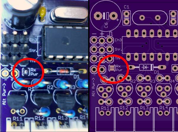
There are two options to power the LED outputs: use the same voltage that comes from the receiver, or use an external power supply. Almost all users will want the first option. To accomplish this, you must remember to solder the small SMD jumper on the board labelled “Rx Pwr.” Simply put a blob of solder over both pads so they are bridged. It is much easier to do this before you solder the other components!
Otherwise, if you prefer to use a different power source for your LEDs, leave the solder jumper alone and install a 2-pin header at the “Alt Pwr” location. Connect your alternate power source to these connections.
Low Voltage Receivers
Some modern receivers are now running at 3.3 volts. This does not mean your OSL board will be powered at 3.3 volts! The positive and negative pins of the receiver's servo outputs will still have whatever voltage is feeding the receiver - typically this is the BEC on your electronic speed controller, and usually that is 5 volts. However, what will be 3.3 volts is the signal from the receiver to the servo/OSL. Sometimes this discrepancy between the processor running voltage and the incoming signal voltage can prevent the OSL from correctly interpreting the incoming radio commands.
A possible solution to this problem is to add a second diode to the OSL board to drop the voltage of the processor. Diode D1 on the OSL board is a standard 1N4148 diode. It serves to drop the voltage to the processor by approximately 1 volt, which means that as designed the processor is already running 1 volt less than the source voltage from your BEC. But if you suspect you are having the problem described above, you can add a second diode in series with the first, which will drop the voltage even further, and hopefully bring it closer to the signal voltage. Of course the board only has holes for a single diode, so you will need to be a little creative, solder the two diodes together first end-to-end (solder the cathode of one to the anode of the other), and then solder the two remaining free ends into the holes on the board (respecting the polarity).
Other Board Designs
Other users have created different versions of the OSL board and they can be found on this page: Other User Designs of the OSL
